Basic HTML Version


557
IBRACON Structures and Materials Journal • 2012 • vol. 5 • nº 5
S. S. Araújo | G. N. Guimarães | A. L. B. Geyer
Tests with the dial gages and strain gages were done at Carlos
Campos Laboratories and tests with clip gages and LVDTs were
done at Furnas Centrais Elétricas Laboratories. It was not possible
to conduct all tests at the same laboratory due to physical and op-
erational constraints (equipment, operating hours, operator avail-
ability, storage) of the two laboratories involved and the quantity of
specimens to be tested.
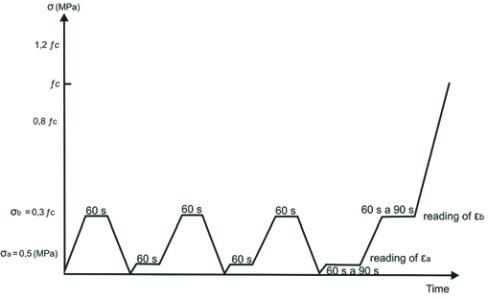
The loading stages known as Metodology A in code ABNT NBR
8522:2008 [3] was used for the modulus of elasticity tests. Cycles
of loading and unloading were done. According to Figure 3, strain
measurements were taken at stress levels of 0.50 MPa and 30%
of the rupture stress (known as f
c
) and the initial tangent modulus
was calculated according to Equation 1.
Conventional concrete Class C30 and Class C60 were used. These
were cast in concrete mixers with a maximum capacity of 450 liters
using Portland cement Type V ARI (high initial strength) fabricated
by CIMPOR. Silica fume, superplasticizers and polyfunctional ad-
ditives were also used in the concrete mix. The properties of the
additives and admixtures used are presented in Table 1. The mix
proportions are presented in Tables 2 and 3. All specimens were
cast at Carlos Campos Laboratories.
Ten cylindrical specimens were cast for compressive strength tests
for each type of concrete (class C30 and C60), for each specimen
dimension (100 mm x 200 mm e 150 mm x 300 mm) and for each
laboratory, for a total of 80 specimens. These tests were done in
the two laboratories (40 specimens tested in each laboratory) at 28
days after casting. The compressive strength test is needed prior
to the modulus tests so the value of 30% of rupture stress can be
calculated for use in the modulus tests and in Equation 1. The rup-
ture stress was calculated as the average of the rupture stresses
of the 10 specimens.
Ten cylindrical specimens were cast for the modulus of elastic-
ity tests for each measurement device (4 different devices), for
each type of concrete (class C30 and C60), and for each speci-
men dimension (100 mm x 200 mm e 150 mm x 300 mm), for a
total of 160 (10x4x2x2) specimens. Tests using the dial indicators
and strain gages were done simultaneously on the same concrete
specimen, so not all specimens cast were used. This was possible,
since, during the test, the analogical readings from the dial indica-
tors were obtained visually by the operator, and the strain gage
readings were digital and obtained using a microcomputer.
All tests were done 28 days after casting. The modulus test is non-
destructive and the same specimen was then taken to rupture to
is mechanically fixed to the surface through claws, permitting their
reuse. The strain gage is disposable after the test. The linear vari-
able differential transformer is better known by its acronym LVDT
and it is an electro-magnetic displacement transducer. Figure 2
shows photos of these 4 measuring devices.
As far as loading speed, code ABNT NBR 8522:2008 [3] specifies
a loading speed for the modulus of elasticity test at (0.45±0.15)
MPa/s. The laboratory where the test is undertaken chooses the
loading speed. In the research, the loading speed used was 0.6
MPa/s at both labs.
2. Experimental program
Considering the characteristics of the interlaboratory program,
three variables were considered:
n
Type of conventional concrete (class C30 and class C60);
n
Type of strain measurement device (dial gages, strain gages,
clip gages and linear variation displacement transducer - LVDT);
n
Cylindrical specimen dimensions: 100 mm x 200 mm and 150
mm x 300 mm.
Figure 2 – Dial Indicators (a) Strain gage (b), Clip gage (c) and LVDT (d)
A
B
C
D
Figure 3 – Loading history for determining
the modulus of elasticity – Method A
(ABNT NBR 8522:2008)

