Basic HTML Version


822
IBRACON Structures and Materials Journal • 2012 • vol. 5 • nº 6
Design of compression reinforcement in reinforced concrete membrane
(2)
n
sy
=n
y
+n
xy
.cotgθ
(3)
n
c
=n
xy
.(tgθ+cotgθ)
(4)
ε
y
ε
x
=tg²θ.
[
1+ ε
c
ε
x
.(1-cotg
2
θ)
]
From these expressions, it is possible to demonstrate that the mini-
mum reinforcement required to equilibrate the tensile stresses in
the membrane occurs when angle
θ
is equal to 45° in case the re-
inforcement is subjected to tensile stresses in x and y. The demon-
stration of this result can be found in several works as in Leonhardt
and Mönning [13], Chen [11] and Jazra [12].
3.1 Cases of design
The CEB [3] divides the design of membranes into four cases.
Case I considers that the reinforcements are subject to tension in
both directions, making n
sx
and n
sx
positive.
When one of the forces in the reinforcement takes negative values
,
i.e. compression, the use of reinforcement in that direction is not nec-
essary. If there is no tensile force in the x direction, case II of design
applies. If there is no tensile force in the y direction, applies case III.
3. The dowel effect will not be considered
4. The effect due to aggregate interlock will not be considered
5. The bond between reinforcement and concrete is perfect
6. The tension-stiffening effect will not be considered
7. The directions of principal strains and the directions of principal
stresses coincide
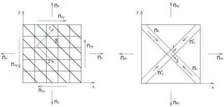
Considering a membrane element subjected to normal forces per unit
length, n
x
and n
y
, and shear force also per unit length, n
xy
, wherein the
reinforcements are positioned in the direction of the x and y axes. Angle
θ
is formed between the principal direction of compression in concrete
and the y direction. In case the element is cracked, angle
θ
is formed by
axis y and the direction of cracks because, as hypothesized, there is no
shear stress between the cracks. Thus, the axis of the principal com-
pressive stress in concrete coincides with the axis parallel to cracks. By
hypothesis, the principal directions of strain and stress in concrete are
considered coincident. This configuration is shown in Figure 1.
Forces n
sx
and n
sy
are positive when they represent tension. When n
c
and n’
c
are compression, they are positive. n’
c
is the minimum com-
pression in the element, when existing, and n
c
is the maximum com-
pression. Figure 1 also shows this convention.
The problem consists in knowing forces n
x
, n
y
and n
xy
, finding the nec-
essary area of reinforcement a
sx
and a
sy
and verifying if compressive
stress in concrete is below its strength. For this purpose, the equilib-
rium and compatibility equations will initially be written for the situation
in which the reinforcement is subjected to tensile stresses in the x
and y directions. This result in expressions 1, 2, 3 and 4, where n
sx
and n
sy
are the forces in the reinforcement in the x and y directions,
respectively, and
ε
y
and
ε
x
are the strains in x and y and ε
c
is the strain
in concrete in the direction of principal compressive strain.
(1)
n
sx
=n
x
+n
xy
.tgθ
Figure 1 – Positive membrane forces and axes considered in this paper