Basic HTML Version


162
IBRACON Structures and Materials Journal • 2013 • vol. 6 • nº 1
Concrete compressive characteristic strength analysis of pile caps with three piles
2.4 Analysis method
The Newton-Rhapson method was adopted in the numerical
analysis, with a uniform load at the top of the column’s cross-
section and force increments of 50 N/cm
2
. For the elements,
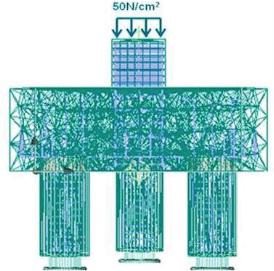
a tetrahedral finite element mesh was adopted as shown in
Figure 5, since the pile caps have a cylindrical mesh and AT-
ENA software only generates hexahedral forms for prismatic
elements.
The structure’s load and displacement monitoring points were fixed
respectively in the center of the column’s superior cross-section
and in the center of the pile cap’s inferior section.
The piles vertical movement was restricted in all of their inferior
cross-section as shown in Figure 5. In the contact-faces of the pile
cap with the piles and with the column, a 3D element interface based
on Mohr-Coulomb criterion was adopted, as shown in the table 5.
3. Results
3.1 Stiffness and bearing capacity
All three models displayed intense cracking in the pile cap’s inferior
Figure 4 – Concrete constitutive laws
Stress
versus
opening cracks
curve (ATENA)
A
Plastic strain (ATENA)
B
Tension stiffening curve [2]
C
Table 3 – Reinforcement properties
Poisson’s
ratio
(
)
0,3
Modulus
of elasticity
(E )
s
210 GPa
Ultimate
tensile
strength
(f )
yk
591 MPa
Yielding
(
)
yd
0,207%
Ultimate
strain
(
)
lim
1%
Table 4 – Steel plates properties
Poisson’s
ratio (
)
0,3
210 GPa
591 MPa
Modulus of
elasticity (E )
s
Yielding (f )
yk
Figure 5 – Details of the finite element mesh,
the supports and the applied load (ATENA)

