Basic HTML Version


854
IBRACON Structures and Materials Journal • 2012 • vol. 5 • nº 6
A study on the behavior of beam-column connections in precast concrete structures:
experimental analysis
3.2 Construction of models
The assembly sequence of Model 1 was as follows (Figure 7):
1. Attaching the beams in the dowels, which were located in
the corbels;
2. Filling the beam-column interface and the hole of the dowels
with grout;
3. Placement of continuity reinforcement and filling the column
hole with grout;
4. Bonding of strain gages;
5. Assembly of timber shapes;
6. Concrete casting.
The assembly of Model 2 was more complex due to the presence
of the slab requires that more time for its construction. Apart from
the construction of the slab, the correct positioning of the negative
reinforcement also needed to be done with care and precision. The
assembly sequence followed the steps listed below (Figure 8):
1. Placement of the beams;
2. Placement of the continuity reinforcement and the filling of the
holes of the column, the holes of the dowels and the beam-
column interface with grout;
3. Assembly of the hollow core slab;
4. Assembly of the reinforcement in the lateral of the column and
the transverse bars;
5. Instrumentation of the continuity reinforcement;
6. Placement of the steel mesh;
7. Assembly of timber shapes;
8. Concrete casting.
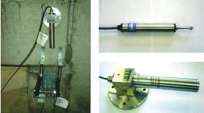
3.3 Instrumentation
In the tests, various measurement instruments were used, each
Figure 8 – The assembly sequence of Model 2
Figure 9 – Rotation measuring instruments (clinometers and transducers)