Basic HTML Version


287
IBRACON Structures and Materials Journal • 2012 • vol. 5 • nº 3
W. R. L. da Silva | J. Němeček | P. Štemberk
dure was held the same as described in section 2.3.1. The speci-
men was cut out from the middle section of a larger volume by
using a precision diamond saw. Then, dried surfaces were grinded
by SiC papers (grit #2000 and #4000) and polished by cloth with
0.25 mm diamond spray. Finally, the surfaces were cleaned by
washing in alcohol and ultrasonic bathing. The resulting surface
roughness (root-mean-square) was checked with AFM to be less
than 20 nm on 5×5
m
m area.
The nanoindentation measurements were carried out in the CSM
Nanohardness tester
®
machine. The three-sided pyramidal indenter
tip (Berkovich) was used to perform a massive grid of 16×18 (288)
indents with the mutual distance of indents of 8 µm as illustrated
in Figure 4a. The indentation location was selected carefully by
a high magnification optical microscope prior to testing to ensure
that they lie away from large aggregate. The microstructure at the
selected location consisted of all the cementitious matrix phases in
Table 4 – Mixing procedure
Procedure
Time (s)
Dry materials mixed together
→
→
→
→
→
→
30
Addition of water
30
Mixture of materials and water
60
Edge shovel clean
30
Addition of superplasticizer
30
Mixture of the base mortar
90
Figure 1 – Elastic modulus tests: (a) specimen dimensions and (b, c) experimental setup
A
B
C
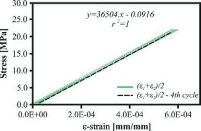
Figure 2 – Elastic modulus: (a) elastic loading cycles and
(b) example of compressive stress-strain curve in elastic regime
A
B

